Intertek Testing ServicesBuilding Automation
In 2014 Johnson Heating and Cooling L.L.C. was contracted to install a building automation system that would control the mechanical systems for Intertek Testing Services, located in Plymouth, Michigan.
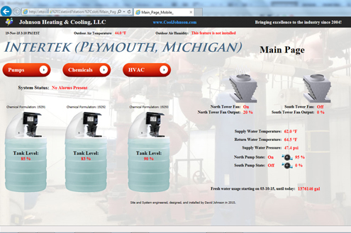
BAS PageBuilding Automation System- Overview
Over $50,000.00 per day is what would be lost if our/this system failed, and tens of thousands of dollars are lost for every interruption of the system’s operation.
While unknown to many, Intertek Testing Services is a very big company that puts their hands on many pieces of consumer products, and simply stated, many products in general. Underwriter’s Laboratories is one of Intertek’s competitors, and Intertek’s facility in Plymouth is pretty large, if not in terms of size, then certainly in terms of heat transfer equipment. While I’m not especially privy to the ins and outs of large specialty equipment pricing, it’s probably a safe bet to say that the Plymouth, Michigan branch of Intertek has something like hundreds of millions of dollars of water cooled equipment “buzzing away” all day long, and 365 days a year. Intertek Testing Services tests products for a variety of customers, and for a variety of purposes, which include: safety, life span, RFI, etc. In addition to testing, analyzing, and simply blowing things up, they shake, rattle, and roll things too.
Some time back in early 2014, we were contracted to install two very large variable frequency drives (VFDs) which control the pumps that supply water to all of the water cooled equipment on-site, as well as a building automation system to operate much of the operation-critical equipment. There was an old automation system in place, which was an absolute disaster & probably didn’t even function (we didn’t bother to check), so we proceeded very carefully. Of the upmost importance was that the operation of the equipment was not interrupted, as operations were underway 24/7/365, and any interruption would result in tens of thousands of dollars in loss, with daily losses in operations totaling over $50,000.00 per day. When considering the potential impact of any sort of “mess-up” or interruption caused by poor engineering or systems design, one can understand that mechanical work can be more stressful than one might expect. To date, however, the systems have never gone off-line, for any reason other than a total building power outage, and operations have never been interrupted, so we did it right.
Building Automation System- Variable Frequency Drives
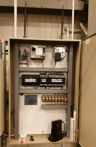
For the 125 horse power (HP) variable frequency drives (VFDs), we went with quality and used Honeywell NXS series VFD’s. We chose Honeywell NXS drives because we’re familiar with them and also because their integration via the LON interface provides unparalleled interoperability to building automation systems. The Building automation system at Intertek, Plymouth is capable of pulling a vast array of information from the VFD’s and is also able to reprogram the devices remotely, in the event of equipment failure. Load calculations, real-time motor efficiency ratings, and energy savings, may all be calculated with the data obtained due to the VFD’s LON communication interface. Because of the “stakes” involved in maintaining the uninterrupted operation of the pumps and the VFD’s which control the pumps, we installed blank displays on the VFDs so that no “passersby” could mess up the system via the display module, which can be used to reprogram the VFDs.
In an effort to give a little background on VFDs, I’ll write the following, however, if you’d like a more comprehensive and basic explanation on what VFDs are and how they function & save money, then I invite you to read about the Clawson Manor building automation system, wherein VFDs are generally explained. On this project, since it’s already been noted that the pump motors are 125 HP motors (which is about the size of a V-6 car engine), it’s obvious that the motors consume a great deal of energy and also that they are quite expensive motors/pumps. The reason why we installed VFDs in the first place was four-fold.
Firstly, the existing system was capable of providing more capacity than what was needed. The system pressures with the pumps operating at 60 Hetz was typically about 53 PSI, which is a whole lot of pressure. It made sense to cut the capacity down in an effort to save electricity and also to reduce wear on the motors and pumps. As explained in the write-up on the Clawson Manor project, the output of the VFD’s, in terms of percentage of frequency, is not linear in terms of the VFD’s energy consumption. For example: 0 Hertz is 0% output, 60 Hertz is 100% output, and 30 Hertz is 50% output, while 0% output may equal 1% FLA of the motor (because the drive itself uses some energy), 50% may equal something like 20% of the FLA of the motor, and 100% output may equal something like 101% of the motor’s FLA. So, by reducing the output of the pump motors to less than 100% output, we were able to effectively cut the energy consumption of the VFD/motor combination to an amount significantly less than the FLA of the motor multiplied by the output value. It’s a confusing concept, so to summarize the matter; the pumps are currently running at something like 90% output, which means that the VFDs would be providing something like 54 Hertz, thus the energy consumption of the motor/VFD combination is not 90% of the FLA of the motors, but rather is something like 70% of the FLA of the motors.
The second reason why we desired to install VFD’s on the pumps is very complex, and again, I’ll ask that you refer to the Clawson Manor project’s explanation of delta T, for some additional back-ground on this subject. Like the Clawson Manor project, our eventual goal is to increase the difference in temperature (“delta T” or “∆T”) of the supply and return line of the open evaporative cooling system. The word “eventual” is used because the structure has many pieces of equipment, all with inconsistent piping configurations and the change in the total equipment state would/will take time. The equipment inside the facility, and the piping inside the facility, is of two types, three way systems and two way systems.
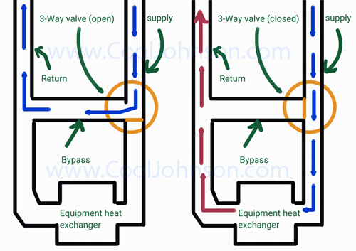
Three way systems are older and less efficient piping configurations, wherein the water going thru the supply line is either sent to the equipment, and then into the return line (after the water has either picked up or removed heat), or is simply diverted directly into the return line (bypassing the equipment). Three way piping systems are less efficient, but were used nonetheless because of the lack of good control systems in the industry. Today three way piping systems are still used, but often because either the efficiency losses are negligible and do not warrant the investment of expensive equipment used for the control of the supply line’s head pressure, or because the three way piping system’s purpose is such that the three way piping system is the best fit for the application (such as may be the case for very accurate loop temperature control), or, and as is most often the case, because the installing contractor and/or the designing engineer has poorly built or designed the system, respectively. There certainly is a place for the proper use of three way valves in this industry, but most often they are used incorrectly and inefficiently, as such is/was the case in Intertek’s hydronic piping system.
Two way valves/systems are defined as systems wherein the water may flow when the valve is open, but then ceases to flow when the valve is closed. Modulating two way valves may be used, however, they are still two way piping systems. A major consideration in two way piping systems is the fact that some provision needs to be made for the relief or control of system head pressure, or else equipment failure may result. Two way piping systems, coupled with some provision for head pressure control are preferred over almost all three way systems, and are also preferred over almost all two way piping systems that have provision for head pressure relief (and not head pressure control). VFD’s allow for the modulation of pumps, and in turn provide an excellent means of modulating and controlling head pressure.
It’s understandable to most that the greater difference in temperature (or delta T) between two substances, the greater the rate of heat transfer, between the two substances, may be observed. For example; picture a cold glass of water, with a few ice cubes, sitting on the ground in the Sahara desert at mid-day, and consider how long it will take for the ice cubes to melt. Likewise, consider the same glass of water sitting on the ground in Michigan, in the fall, when outdoor air temperatures are somewhere around 40 degrees F, and consider how long it will take for the ice cubes to melt. It’s obvious that although the same measure of energy is required to melt the ice cubes, they will melt much faster in the desert. While it’s simple to understand this concept, while looking at two extreme examples, it’s not always easy for some to understand this concept while looking at two examples with differences of only a few degrees, or even a few tens of degrees.
Such as a two way piping system causes all the water to pass through the heat exchanger of the equipment, which typically causes the water temperature to rise, and such as a three way piping system diverts the water back into the return line, so that the inlet temperature and the outlet temperature of the circuit does not change in temperature, it’s understandable that if dozens of pieces of water cooled equipment are set up with two way piping systems, there will be a greater difference in temperature between the inlet and outlet temperatures of the primary lines, which feed the equipment. Inlet and outlet may be replaced with supply and return, respectively.
It’s desirable to have the inlet (supply) and outlet (return) to have the greatest difference in temperature because the warmer the outlet or return temperature is, coming back to the evaporative cooling system, the more effective the evaporative cooling system will be at transferring heat from the water to the air and water vapor, which is evaporated. Additionally, the use of two way systems means that less water is actually being pumped, so the pump output could be dropped, while still maintaining the appropriate head pressure. The project is an ongoing work, such as much of the piping needs to be examined and some needs to be reconfigured.
The third reason why it was desirable to install VFD’s to control the pumps is very much related to the second reason. As previously explained, some of the equipment which uses the hydronic system is set up with two way piping or valving, wherein the water supply going to some of the equipment was either on or off. Such as this is the case, and such as the equipment operation is random and uncoordinated, what would happen from time to time is that sometimes there would be very few branch circuits requiring flow, which would increase the head pressure of the main lines. When one line would allow for flow, and then suddenly cease the flow, a “water hammer” effect could be observed, wherein the main lines would actually swing near the ceiling. As noted, the cost for operations down time is quite significant at this facility, and nearly every piece of equipment is water “cooled”, so if the swinging of the main lines caused one of the rubber seals in the Victaulic fittings to break, such a break would be very expensive because it would necessitate ordering a special order fitting, probably from out of State, having rush delivery, removing all of the water from the thousands of yards of lines, removal of the line or fitting (ranging in size from 1” up to 22”), and the repair of the lines and/or fittings. Also considerable, there would not only be the incurred expense of the labor and materials needed to make the repair, the expense incurred due to the loss of operations, but also the expense of the damages caused by something akin to having a fire hydrant expelling water inside the facility.
The swinging of the primary piping due to the “water hammer” effect was not only potentially costly, but also a significant safety hazard. While having a large volume of pressurized water blasting on someone isn’t much of a big deal, electricity, and the possibility of a thousand pound pipe landing on one’s head is. All in all, our solution resolved the matter in a safe, cost effective, and profitable manor.
The forth reason why it was desirable to install VFDs to control the pump motors is one of convenience. The Honeywell NXS VFDs provide unparalleled control via the LON bus option card. Switching pump duties, changing head pressure set points, monitoring pump energy consumption, and alarming is all easier and better accomplished with VFDs and the automation solution which we provided. Remote control is useful in situations like power outages on a Saturday night, as has been the case at least once since this system has been installed.
Building Automation System- Communications
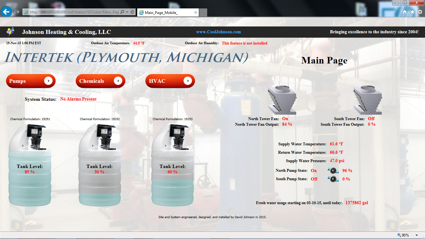
Because Intertek does confidential testing of proprietary technologies and products, we were not allowed access to their local area computer network (LAN), so that we could set up and access our automation server from the wide area network (WAN), which is commonly called the internet or the World Wide Web (WWW). Since it was important to Intertek that we have provision to access the building automation server remotely, for the purposes of providing more cost effective programing services, more thorough monitoring, the ability to generate and send alarms via e-mail and text message, and to provide remote assistance and troubleshooting, we installed a mobile internet modem with a battery back up on the entire system. The system is configured such that Intertek employees and Johnson Heating and Cooling employees have many points of access to the system, which include cellular phone (smart phone) access over the WAN or WWW, touch screen interface access (located at the server), computer access either via the wireless LAN in the server room or over the WAN from any location.
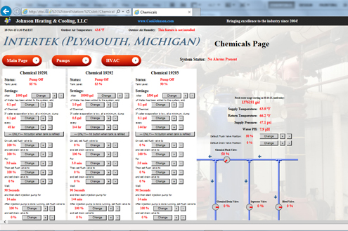
Building Automation System/Chemical Treatment Program
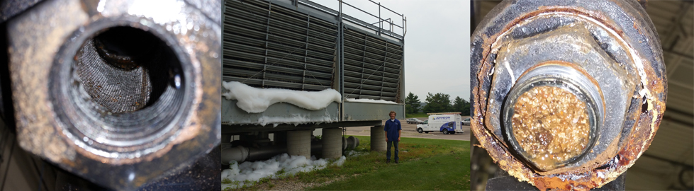
During the process of installing the automation system for Intertek we found that the evaporative cooling system’s bleed timer was inoperative, and had been for some time. The batteries in the device had exploded, such as batteries do when they are fully depleted and very old. We found the total dissolved solids (TDS) in the system were not being bleed, and that the Y-strainers in place just before the equipment in the facility, were nearly completely plugged up with debris from the system. Because we have over a decade of experience in chemical treatment programs we jumped right into addressing the issues concerning the water condition of the evaporative cooling system.
Because we did not have time to prepare in advance of the of the cancelation of services of the previous chemical treatment program provider, we did not have time to get all of our material “in-stock” before our tenor of the system began, but we made due with what we had and began our work. The first thing we did was to shock the system with an acid treatment in order to kill any microbials that might be in the system, since we didn’t know exactly what formulations the previous chemical treatment program provider was using or if his program was adequately killing the microbials (since we didn’t investigate his dosing regiment in much detail before the termination of his services). After insuring that the system did not harbor harmful and potentially deadly microbials we proceeded on the long course of rectifying the problems with the system.
Once we ensured that the system was safe in terms of the immediate threat caused by mircobials, we ordered the materials, equipment, and chemicals needed to put in place a proper chemical treatment program. As noted on the chemical treatment page of this site, we make our own chemicals, to the extent that we understand the formulations needed & we purchase the raw materials needed to formulate effective ends, according to our customers’ needs.
As noted above, we found that the controller which was responsible for performing the bleed regiment (in order to reduce the TDS in the water) was non-functional, so we integrated the control of the bleed valve into the building automation system. Also, we found that in addition to the bleed valve being non-functional, the separator’s blow off valve was non-functional and that sediment had become cemented at the bottom of the separator, probably because it had not been used in years or even tens of years. The separator is a large cylinder shaped, steel pressure vessel, which causes heavy sediment and debris to sink to the bottom of the pressure vessel. The water enters the side of the separator, near its top, and exits the separator via the top. Debris sinks to the bottom of the vessel, where it is in turn expelled from the system by piping on the bottom of the vessel, of which the flow is controlled by the separator blow-off valve.
Of note; one thing that we did not notice in the old chemical treatment program was the use of poly chemicals, the purpose of which is to protect the internals of the system from scale build up and also corrosion. That being noted, and given that there was neither a proper bleed regiment nor a proper “blow off” of the separator, it’s almost needless to say that the system was a complete mess both in terms of mineral deposits and in terms of corrosion deposits. The corrosion which had taken place in the system had not evidenced itself in the form of leaks, which is incredibly fortunate for the customer, however, time will tell, as to the extent of the damage done. It’s a fortunate thing that during the era in which the system and piping was build, things were done “heavy and strong”, so the system is obviously quite well suited for taking abuse. Furthermore, the TDS in the water and also the scale may have been a major off-setter of the corrosion which may have otherwise taken place. It’s not to say that scale is generally good, because it certainly is not, however, in the regard of preventing corrosion in an untreated system, it may have helped.
We integrated the separator’s blow off valve into the automation system, but when it came time to use the valve we found that the separator had cemented sediment at its base, which prevented the function of “blowing off” the separator, even under 50 PSI of pressure. We had to do something which was not only nerve racking, but also dangerous. We had to free the sediment from the bottom of the separator, while the system was under pressure. We accomplished this by injecting high pressure water into the underside of the cemented sediment. The release of the sediment was sudden and shocking, even though we had the gate valve open only some ½” or so. The reason why we left the system online was because the systems down time would cost so much money, which again proves our commitment to act in our customers’ best interest.
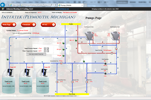
Once the materials for the chemical treatment program arrived, we integrated the pump and valve control into the automation system. Things like gallons of water used, chemical tank level, and supply temperature set point were all integrated into the automation system. The system controls four VFDs in total, two for the system pumps, and two for the evaporative cooling towers fans. Also controlled are the butterfly bypass valves which bypass the water from going to the water tower in the winter, but only if the supply temperature is within range. A PH sensor was installed so that the PH of the water could be observed during the course of certain chemical treatments.
The integration of the evaporative cooling tower’s fan motor VFD’s will prove to save much both terms of the longevity of the equipment (fans, motors, belts, bearings, etc.), but also in terms of the energy consumption of the system. Nuisance manual resets of the (10 year old) fan motor VFDs were eliminated because we reprogramed the VFDs and changed their mode of control. Previously, the fan VFDs would need to be manually reset for even the briefest power interruption, resulting in the interruption of some of the operations of the facility.
In terms of the chemical treatment program we restructured the piping such that rather than dumping the chemicals into the system at a rate of something like 0.4 gallons per hour, we applied the chemicals into a holding reservoir and then flushed the chemicals into the system all at once, via 50 PSI water supplied by the system. The end result was that the chemicals would allow for a rapid and drastic drop in the PH of the whole system, rather than to neutralize gradually and achieve only slightly acidic PH while being administered. The benefits of the rapid and drastic reduction of the PH of the water are basically two-fold. Firstly, with the rapid and drastic reduction of the PH, the microbials in the system are more effectively killed. Secondly, with the rapid and drastic reduction of the PH, mineral deposits and scale may be more effectively broken up.
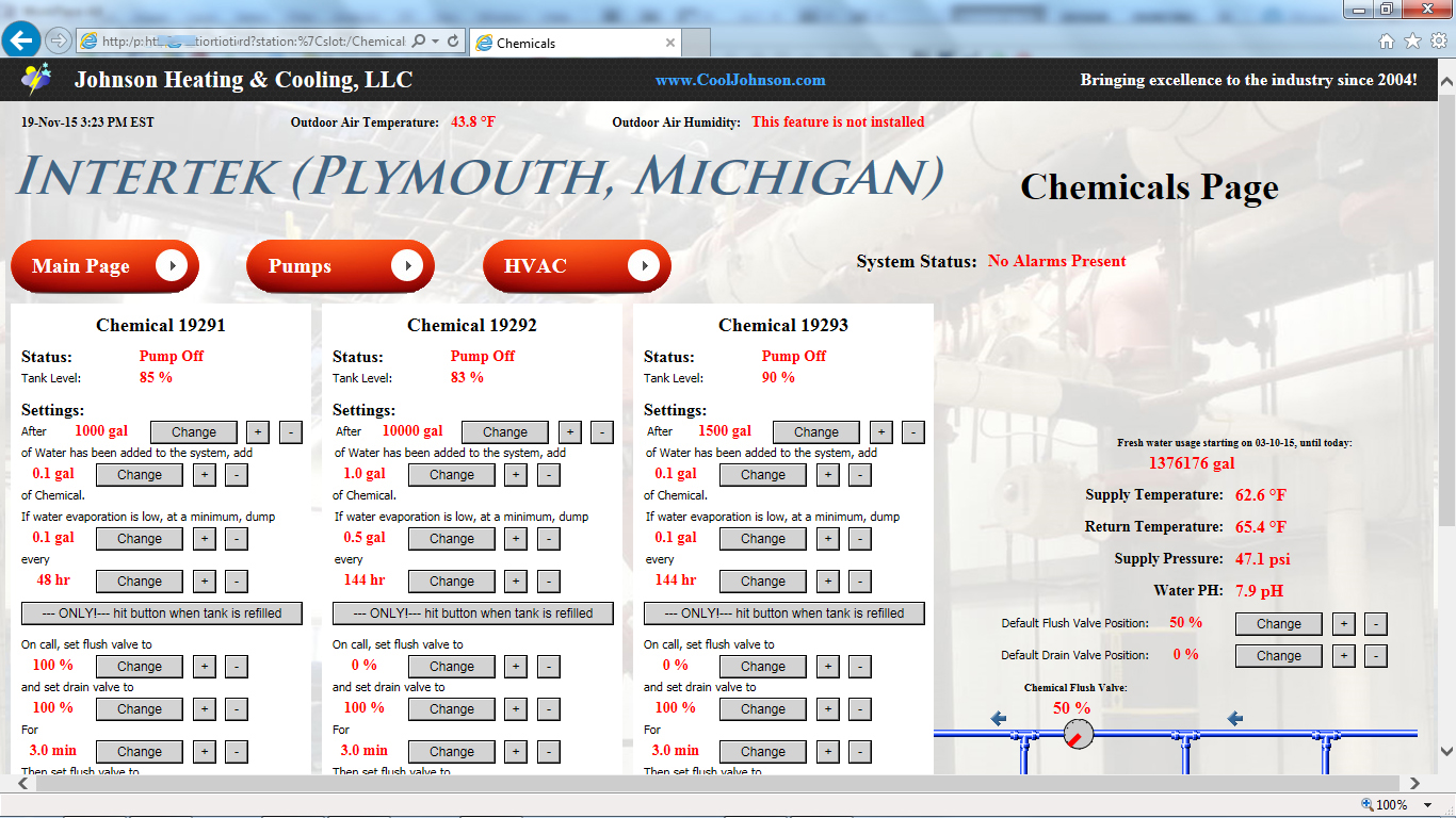
With the integration of the chemical injection regiment, we did something which is not typically done in the industry; we gave the customer options. While we do not allow for others to change the settings which we’ve placed in the chemical treatment program, we have very clearly structured the graphical user interface (GUI) so that nearly every critical aspect of the chemical injection process may be modified by those with access to the GUI. It’s as user friendly as possible, and also it’s as simple as it can be. The process and the settings are understandable to a lay person, and those designated by the customer may access the controls to the injection process. While the customer can change the settings in the process, they are not authorized to do so as long as we are responsible for the operation, because of public safety concerns.
Chemical Treatment Program- Scale
A significant aspect of the work done at Intertek was in regards to the removal of scale and debris from the total system. It’s understandable and obvious that the work and improvements done, as detailed in this writing, had a direct and obvious impact of both the energy consumption and longevity of the equipment noted in this writing, but what might escape the notice of some is that this work also impacted every single water cooled piece of equipment in the facility. Scale is a very effective insulator, and as such, only a small “egg shell” coating of scale on a heat exchanger will greatly decrease the thermal transfer rates of that heat exchanger. Additionally if the water flow going thru a heat exchanger is reduced, the thermal transfer rates will also decrease. The condition of the systems at Intertek were such that there was both scale on the heat exchangers, and also reduced water flow going to the equipment heat exchangers.
Because the thermal transfer rates of all pieces of equipment on the system were reduced, every piece of equipment needed to operate its heat transfer components (i.e. refrigeration circuits/compressors) for longer periods of time, to transfer the same amount of heat. The additional run time of the equipments’ thermal transfer components in and of itself added additional heat energy to the equation because, after all, compressors themselves generate heat while they are in operation, and the increased run time equates to increased heat added due to the compressors running.
The increased run time of the heat transfer components in the equipment decreased equipment longevity, and that to an extent which is not easily quantifiable. As any good refrigeration technician or engineer may testify to; when condensers are not able to transfer their heat within appropriate specifications, the result is that that high side pressure will increase, in turn raising the entire system pressure. Simply stated, if the heat exchangers don’t work properly, the system will be warmer and the pressures will go up. The increased pressures cause the compressor windings to heat up more, put more strain on the compressor valves or reeds, and generally wear compressors much faster than that which is normal.
To remove the scale from the system, we administered several applications of chemicals which busted the scale off of the lines, and most importantly, off of the heat exchangers of the equipment in the facility. Once we determined that the system was relatively “scale free”, we removed excessive amounts of debris by flushing each Y-strainer, cleaning the screens on all Y-strainers, vacuuming out debris from the evaporative cooler, “blowing off the separator”, and bleeding the system several times. The entire process took months to do, but by the end of the process we actually got complaints of system pressure and flow rates which were too high, rather than too low- which was music to our ears.
The end result of cleaning the lines and heat exchangers in the facilities systems are all good, however not very quantifiable. The equipment operates more efficiently, longevity has been increased, service work and repair costs have been reduced, and less energy is needed to operate the equipment. Furthermore, thermal shock equipment operates more quickly, which is also important for the facilities ongoing tests and operations.
On first glance, one may not consider all of the facets involved in what is seemingly such a small project, but, just as the writing describing this project is detailed and lengthy, so is the depth and code involved in the building of this automation system. The quality of the work and know-how of the men at Johnson Heating and Cooling, LLC went into this project, and we are proud to put our name on it.