Excel RehabilitationBuilding Automation
In 2012 Johnson Heating and Cooling L.L.C. was contracted to install a new building automation system that would control the heating, ventilation, and air conditioning equipment at a facility operated by Excel Rehabilitation. Johnson Heating and Cooling, LLC also fixed issues with the mechanical systems that where not associated with controls.
BAS PageBuilding Automation System User Manual
Excel Rehabilitation Services
Building Automation System- Getting Started
To effectively operate your DDC system it is important to understand how your system is set up and how it operates. Your system is composed of five groups of different physical components. Also, your system has two different groups of components in which application specific custom programming resides. For starters, we’ll look at each of the five groups of physical components and discuss their functions.
The Server
The server is, essentially, a computer/web server in where most of the system’s custom programming and unit control resides. Typically there is only one server per structure. The server is what the end user interacts with when he logs into the system. The server is responsible for displaying the automated web based graphics, uploading the values from the controllers, downloading values/commands to the controllers, and the sending of alarms. Your server is located in the second floor communications room.
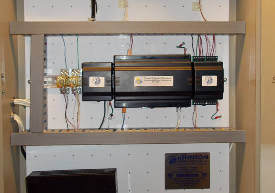
The Controllers
The controllers are devices that command the units’ (i.e. V.A.V. or roof-top unit) operations, retain sensor and wall module values, and communicate with the server. Each unit has one controller, and it is typically located in or near the unit. Essential custom programming for the proper unit operation is located within each controller. Because some of the values/commands that the controllers need come from the server, the controllers’ operation changes when communication to or from the server is interrupted (reference the “Troubleshooting” section of this guide for more information on what happens when the communication between the server and a controller fails). The unit controller is solely responsible for commanding it’s unit, however it’s decision to make a certain command may be based on an outside parameter coming from the server or coming from another controller.
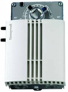
The Digital Wall Modules
The digital wall modules look similar to thermostats, and are located in the area that it’s unit conditions. The digital wall modules do not make any decisions; their only functions are to provide values to the unit’s controller, to display the current space temperature, to display the wall module setpoint on its display, and provide a means for the occupants of the space to put the unit into override. The digital wall modules at each location have one adjustable temperature setpoint wheel, and one LCD display. The buttons on the wall module serve no purpose and do not function.
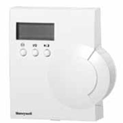
Turning the wall module setpoint wheel sets the occupancy state to occupied, and sets the active space temperature setpoint to the adjustable value that is displayed on the LCD. This value is called the “wall module setpoint” and can be viewed via the computer system under the specific unit’s page. The wall module setpoint can also be viewed by turning the wall module wheel one click, and can be changed by continuing to turn the wall module wheel. Turning the wall module wheel one click displays the wall module value, but does not put the space into override. The override function of the wall module can be disabled on its corresponding web page.
The Sensors
The various sensors in this DDC system provide values to the units’ controllers.
The Bus Line
The bus line is a two (and sometimes four) conductor wire that links all of the controllers to the server and to each other. All communication between the server and the controllers and between individual controllers goes through the bus line. If the bus line fails at a specific point, then all communication that would normally travel through that point will fail.
The two “Brains” of each Unit
Each unit (V.A.V. box or roof-top unit) has two “programmable logic controllers” that control it, and they both work together to decide what commands to make. The two brains that each unit has are the server and the controller.
The controller is only able to function in certain ways. Each controller has an application specific custom program embedded in it’s memory. The embedded program in the controller was designed so that it could be manipulated in such ways (by the program in the server) so that all of the desired system operations could be achieved, while at the same time ensuring the highest level of redundancy in the event of certain system components failing. The controller is set up so that it will control the unit with or without the server, however, without the server, the system is severely crippled. Simply stated, the program in the server’s memory manipulates the programs in the controllers.
Building Automation System- Operating the Program
All of the programs in every device at your building were specifically made for your building with the end user in mind, so navigating through the system and changing values should be fairly easy. The system was designed for several purposes: To provide centralized remote consoles (any computer or smart device with internet access) to change settings and monitor the HVAC systems for the sake of energy conservation and convenience, to provide a means to diagnose or expedite the diagnosis of mechanical failures, and to provide a means of sending out alarms in the event of a HVAC component failure or poor operation.
Logging on to the System
To log on to the HVAC system you must have a computer with internet access, a mouse or some other pointing device, and a keyboard. Go to the following web site www.CoolJohnson.com . Enter the site, scroll to the bottom of the page and locate the “Quick Links” column of links. Click on the link with the abbreviations of your building’s name (5210 Highland). Enter your username and password, and then you’re in.
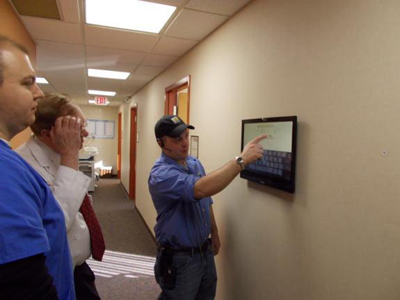
Smart Phones, Tablets, and Touchscreen Interfaces
While designing the graphical user interface for this system, we went the extra mile and fully integrated and optimized the interface for mobile devices. We even went so far as to fix an interface problem in the Honeywell software itself, so that the interface could be more easily operated from any mobile device. If your suite has a touchscreen display interface, you will notice that it functions in the same way as an Android phone. All of the rules and principles of system operation are the same, and this display has been added for your convenience.
Navigation
Navigating though the system is very easy. It is set up just like a common web page, and all one needs to do is point and click. The only pages that do not have return links (that is, the only pages that are dead-ends) are the schedules. When one wishes to return from the schedule page to the previous page, all one needs to do is click on the back arrow of his web browser. Once you log into the system you will see the primary navigation page. From the primary navigation page, one is able to navigate to the areas of the program to which his security level allows him to go to simply by clicking on the link or picture.
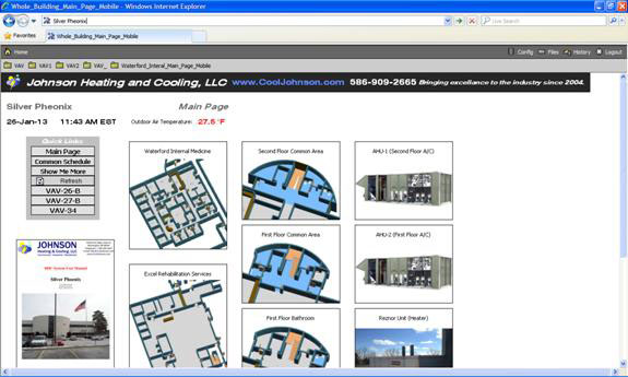
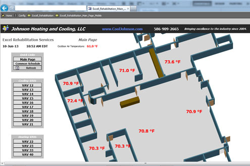
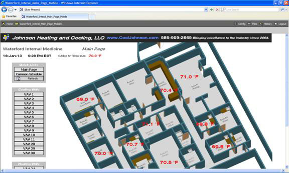
Please note that clicking on the temperature value on the 3-D graphic or map will take you to the VAV that conditions that space.
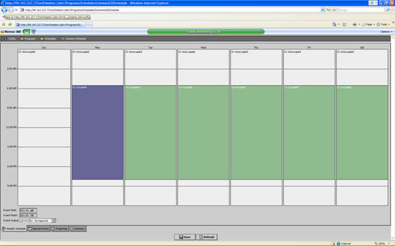
This is a picture of a schedule:
The Program Infrastructure
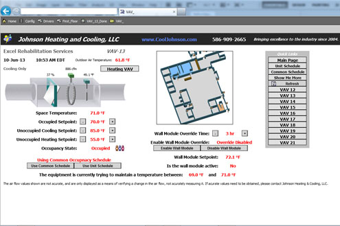
You will notice that may of the graphics look the same from page to page, so it is important to verify that you are actually on the correct unit’s page before making changes or determinations. In the upper left corner of each of the unit pages, there is a name (i.e. “Roof-top Unit”, “Furnace”, “VAV”, etc.) and a number that denotes what unit page you are actually on. When appropriate, the different pages will have 3-D pictures with the correlating conditioned space indicated by a blue background. Please remember that air migrates, so in some places obtaining two different space temperatures in close quarters may be difficult.
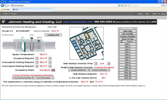
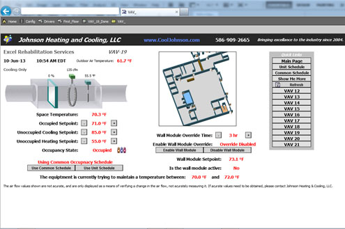
It is very obvious how to change values. Just point and click. Since this program was created with the end-user in mind, almost all of the values and setpoints displayed are very easy to understand, however there are still a few values and functions that may need some explanation, and they are as follows:
Fan Mode- The fan mode setting determines the operation of the fan. When the fan mode is in the auto state the fan only turns on when the unit turns on the heating or the cooling. When it is in the continuous mode, the fan runs all the time.
Space Temperature- The space temperature value denotes the temperature of the air in the area that the unit conditions.
Effective Setpoint- The value at which the unit engages the denoted action. For example; if the effective setpoint is 68oF for “hvacheat”, then the controller will energize the heating circuit when the space temperature is below 68oF, but if the space temperature is at 68.3oF the controller will not energize the heating circuit.
Occupied Setpoint- The controller will try to maintain a temperature between the occupied space temperature setpoint minus half of the dead-band setpoint and the occupied space temperature setpoint plus half of the dead-band setpoint. For example, if the occupied space temperature setpoint is set to 68oF and the dead-band setpoint is 2, then the controller will try to maintain a space temperature between 67oF and 69oF. If the occupied space temperature setpoint is set at 74oF and the dead-band is set to 3, then the controller will try to maintain a space temperature between 72.5oF and 75.5oF.
Wall Module Setpoint- The wall module setpoint is the value which replaces the occupied space temperature setpoint when the controller is in bypass mode. Controllers that are slave controllers receive their wall module setpoint from their master controller.
Wall Module Override Time- This value sets the time that the controller will remain in the override state once the override is activated.
Use Common Occupancy Schedule option- When this value is selected, the controller will get its occupancy values from the common schedule. When this option is not selected, the controller will get its occupancy values from its own (dedicated to only that controller) unit schedule.
Enable Wall Module Override- When this option is enabled, the setpoint temperature will be changed to match the wall module setpoint when the controller’s wall module setpoint temperature is changed. When this override is enabled, the setpoint temperature will be changed to match the wall module setpoint temperature when the wall module setpoint temperature is changed.
Unoccupied Heating Setpoint- When the space temperature is less than this value, and the occupancy state of the controller is unoccupied, the controller will energize the heat circuit.
Unoccupied Cooling Setpoint- When the space temperature is greater than this value, and the occupancy state of the controller is unoccupied, the controller will energize the cool circuit.
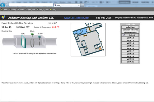
Slave Units
Slave controllers receive many of their values and setpoints from their respective master controller. Slave controllers were programmed this way to avoid setpoint conflicts with other controllers that condition the same space. Slave controllers are in this building are the heating VAVs. When any of the shared values of any slave or master unit are changed, they also change for the other linked slave or master controllers.

Building Automation System- Specific Building Considerations
While operating the building automation system you may notice that some of the VAV controllers report air flow, even while the damper is 100% closed. Also, you may notice that the air flow values reported seem to be inaccurate. The air flow values are in fact inaccurate, and were only included in the graphical user interface for the purpose of verifying a change in the air flow. A unit’s page may report air flow, when in fact there may be no air flow whatsoever. Basically, the VAV’s in this building are of poor design and do not have high quality pressure transducer lines or “pitot tubes”. The new controllers are high quality, but the pressure transducer “pick-ups” or “pitot tubes” in the VAV boxes are not. Because unreliable air flow values effect the operation of the VAV’s, we had no choice but to set the VAV’s to operate based on damper position rather than air flow values.
Air migration will be an unavoidable issue in any building with multiple temperature controllers in close quarters and a non-ducted return air configuration. Keeping space temperature setpoint values at the same value (i.e. 68 degrees F though-out) will reduce energy bills and eliminate hot and cold spots though-out the building.
User error is usually a common problem. Please take the time to understand this system and the basic principles of thermodynamics. Read this manual, and ask questions. Remember to use the unoccupied setting, because turning the equipment off at night and on holidays saves energy and money. Good practice, for the person who maintains this system, is to check the system settings on a regular basis, even if no changes need to be made.
Building Automation System- Troubleshooting
For the most part, this is a “for your information” section of this guide, but it may become useful if anything in the system breaks down (and everything mechanical and electro-mechanical does break down). If there is a problem with your system, 99% of the time we will be the first to know. Because of the alarm programs built into your system, most issues will probably be resolved before you are ever inconvenienced or uncomfortable. First off, if there is a problem with the system give us a call at (586) 909-2665. The following will tell you how to respond to a given situation.
The Connection to the System Fails- When you’re not able to connect to the system, probably one of two things have happened, either the internet connection has failed, or the server has crashed. As long as the server has not crashed the system will continue to operate according to the last values entered into the system. If the server has crashed, than the unit controllers will change the setpoint temperature to match the wall module setpoint temperature, so all of the wall module setpoints should be set to an acceptable value.
A Unit is Malfunctioning- If a unit is acting abnormal, please call us at: (586)909-2665. Your comfort and safety is very important to us. Note: this system is very reliable, and usually we will know of any issues before you do.
Building Automation System- Usernames and Passwords
Usernames and passwords are case sensitive and can be traced, so keep your username and password to yourself. A record of any activity on the server is created each time anything is done on the server. If a setpoint is changed, a record that indicates who changed the value, what the value was changed to, and when the change was made, is created. It is the responsibility of the users to ensure that usernames and passwords are only given to responsible people. Johnson Heating and Cooling, LLC can make changes to any usernames and passwords. To make changes to the log in credentials for your suite, e-mail us, detailing the changes requested, and then call us to verify that we have received your e-mail.
Based on who you are, your access to certain parts of the system may be restricted. For example, the people upstairs cannot modify the setpoints downstairs. Like-wise, access to the roof-top equipment setpoints is restricted to Johnson Heating and Cooling, LLC, the building owner, and his representative.
This content was written by David Johnson and is copyrighted 2012.